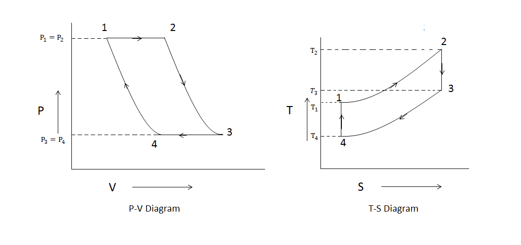
State Diagram For Turbine Engine
Aircraft systems: aircraft turbine engine fuel system requirements Turbine engine thermodynamic cycle Turbocharger rotors turbines cfd innovative
Aircraft Systems: Aircraft Turbine Engine Fuel System Requirements
Turbine brayton compressor cycle engine nasa thermodynamic gas jet plot non why engines glenn gif contact efficiency Turbine gas micro engine diagram mechanical power intechopen market chp internal engineering grows rising use review energy gastopowerjournal generation figure Gas turbine electrical4u
8 flow diagram of a simple gas turbine-steam turbine combined power
Cross-section of the proposed turbocharger how it works? the exhaustMechanical engineering: turbine internal diagram Turbine gas diagram schematic engine figTurbine alstom.
Fuel system turbine engine schematic apu aircraft general valve metering systems pressure requirements differential figure constantGas turbine parts Gas turbine diagram engine natural power plant generation thermoelectric production use energy courtesy educationClosed cycle gas turbine: construction, working, diagram.

Lubrication pressure softinway
Engine parts drawing jet airplane nasa computer turbine gas labeled schematic inside muchTurbine gas diagram cycle closed working pv various booster mechanical construction processes used Schematic diagram of gas turbine power plantCombined turbine ccgt process mohammed.
Brayton state turbojet processesSchematic diagram of a gas turbine engine. T-s diagram of the combined cycle gas turbine ccgt processGas turbine lubrication systems.

Use of natural gas production for a thermoelectric power generation plant
Material types used in different sections in an alstom gas turbineBrayton power cycle .
.

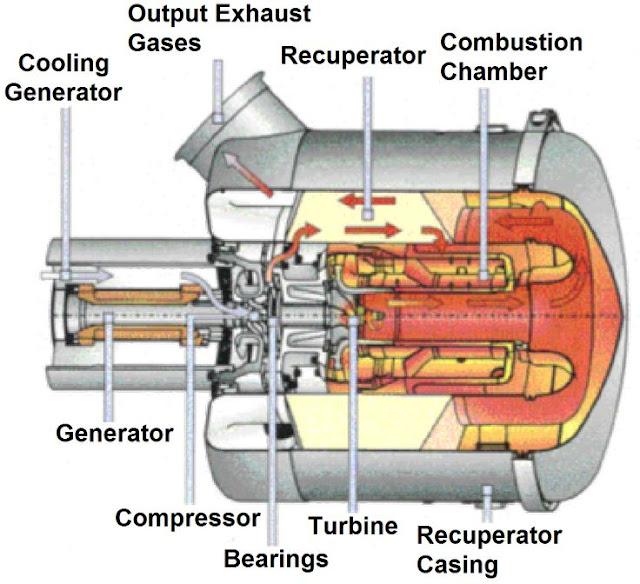
Mechanical Engineering: Turbine internal diagram

Brayton Power Cycle
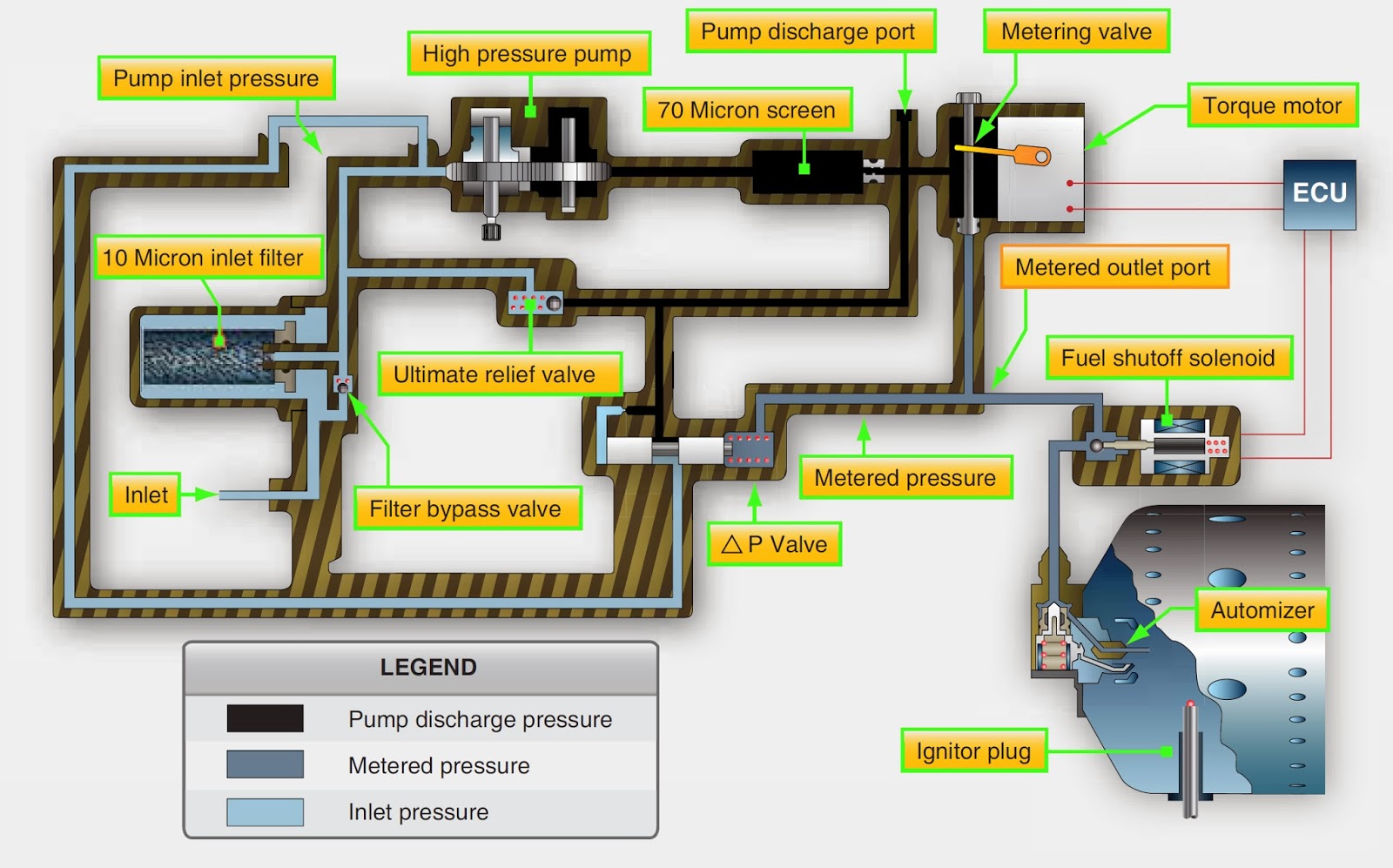
Aircraft Systems: Aircraft Turbine Engine Fuel System Requirements

Schematic diagram of a gas turbine engine.
Closed Cycle Gas Turbine: Construction, Working, diagram - Mechanical

Gas Turbine Parts

Cross-section of the proposed Turbocharger How it works? The exhaust

Use of Natural Gas Production for a Thermoelectric Power Generation Plant

Material types used in different sections in an Alstom gas turbine